
Phasing Complex Treatment for Adolescent Patients with Orthodontic Needs
Patients presenting to to the dental office with widespread enamel defects or congenital enamel hypoplasia can present unique challenges for an operator charged with restoring the compromised teeth to proper form, function, and esthetics. These challenges are exacerbated when the patient is young or adolescent, as transitions through the mixed dentition phase and long-term appositional downward and forward growth of the maxillo-mandibular complex must often be considered. Perhaps one of the most demanding cases to address is a patient who presents with multiple criteria listed above and is in need of orthodontic treatment (figure 1a, 1b, 1c). Addressing compromised hard tissue is paramount in treating these cases, as establishing oral health will provide the basis for numerous future treatment modalities. Moreover, poor enamel quality can compromise the ability of the orthodontic provider to bond brackets when clear aligners are insufficient to address orthognathic discrepancies.

Figure 1a; A panoramic radiograph of the patient

Figure 1b; A cephalometric radiograph of the patient

Figure 1c; A retracted (1:3 magnification) view of the patient’s dentition pre-treatment
The following patient (a 17 year old male) presented with chief complaints related to his bite and the appearance of his teeth. The patient and his parent were both aware of the poor enamel quality, since older siblings have experienced the same condition. Upon initial exam, the following dental problem list was developed:
® Poor enamel quality relating to poor oral health and high caries risk
® Poor enamel quality for bonding orthodontic brackets
® Altered passive eruption
® Abnormal tooth morphology
® Dental caries, attrition, and fracture of tooth structure
® Retained primary teeth O and P with no succedaneous teeth
® Conjoined supernumerary tooth associated with the upper left second bicuspid
® Skeletal inequity affecting facial profile and causing occlusal discrepancy
® Fair oral hygiene and gingival inflammation
® Impacted third molars (#1,16,17) and upper right second molar (#2)
® Dental esthetics
(figure 2a, 2b, 2c)

Figure 2a; A retracted right lateral view (1:3 magnification).

Figure 2b; A view of the maxillary anterior teeth (1:1 magnification).

Figure 2c; An occlusal view (1:3 magnification). Note the conjoined supernumerary tooth on the mesial aspect of the upper left second bicuspid.
The patient was referred to the orthodontist for further evaluation, and the following orthodontic findings were reported:
® Class II Malocclusion
® Poor spacing and tooth size discrepancy
® Severe overjet with deep, impinging overbite
® No TMJ problems found
® Centric Relation appears to be equal to Centric Occlusion
An orthodontic treatment plan was developed. Comprehensive orthodontics was recommended, with a focus on utilizing elastics and Forsus appliances to correct the Class II occlusion. Surgical mandibular advancement would be considered if non-surgical modalities proved to be insufficient in correcting the Class II occlusion. Initially, bite blocks were treatment planned to open the deep bite, but it was decided that an increase in Vertical Dimension of Occlusion (VDO) could be accomplished within the context of the restorative plan. Impressions were taken and casts were made and digitized (figure 3a). Case planning was done in combination with the restorative doctor, the orthodontist, and the digital dental laboratory technician by utilizing 3Shape Software and Computer Aided Design (CAD) (figure 3b).
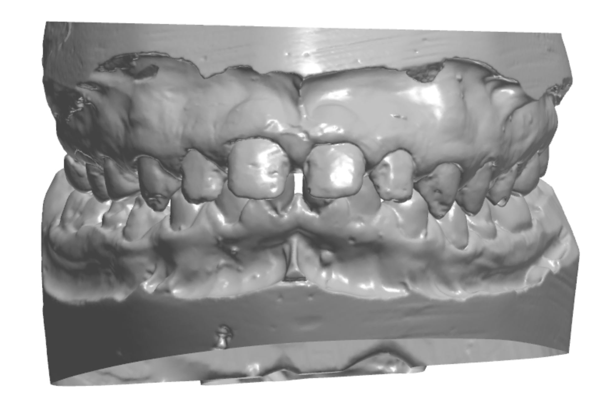
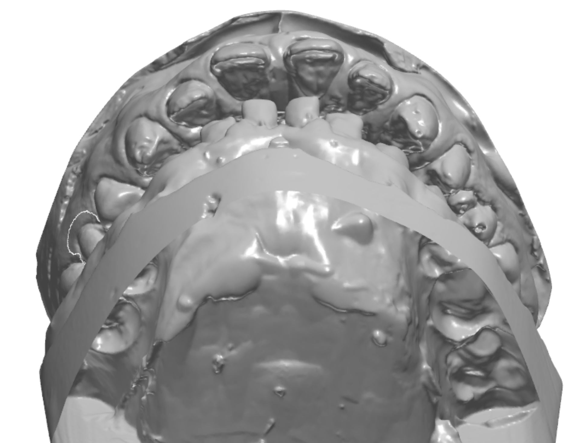
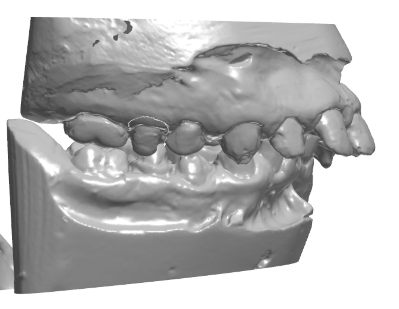
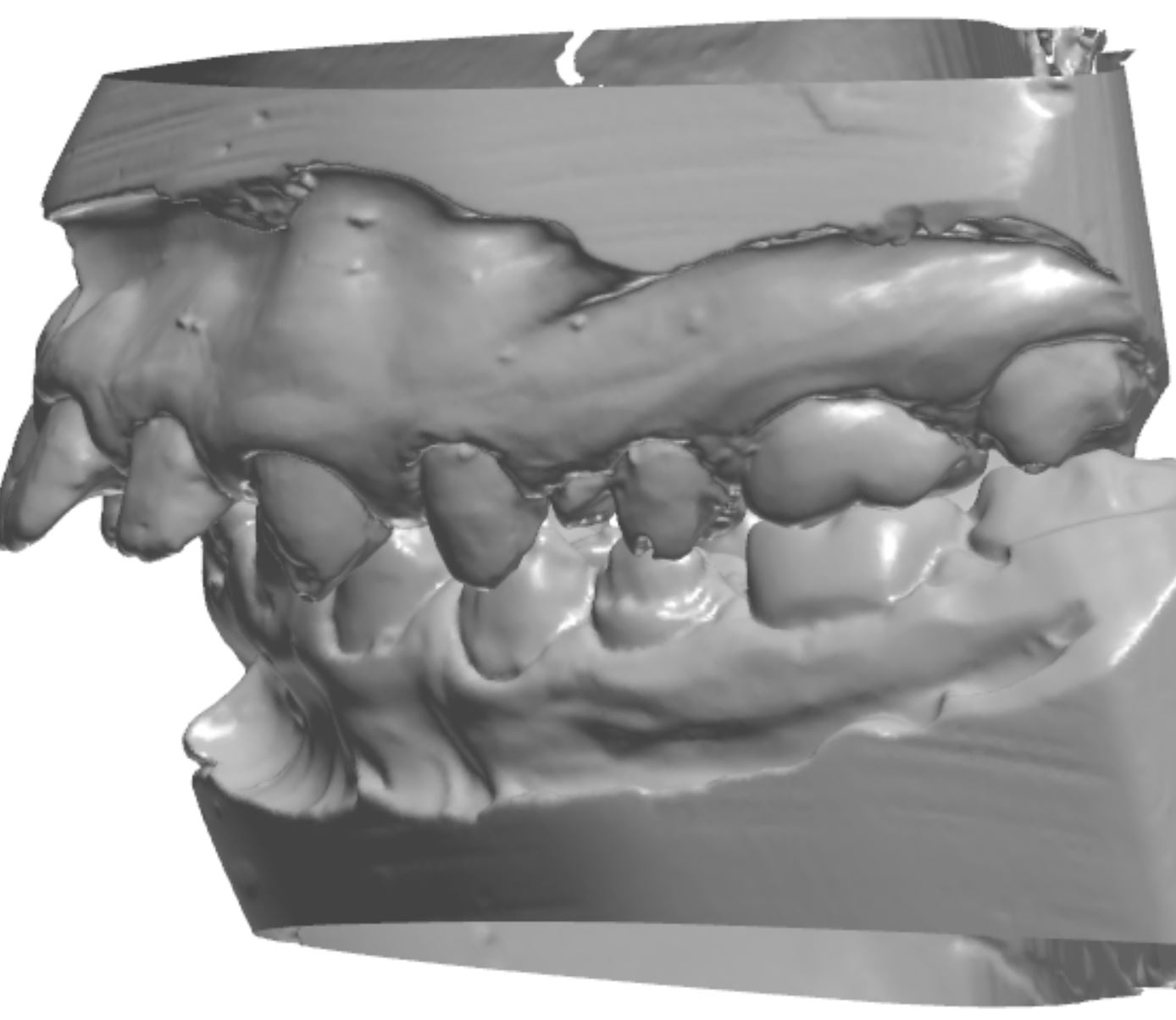
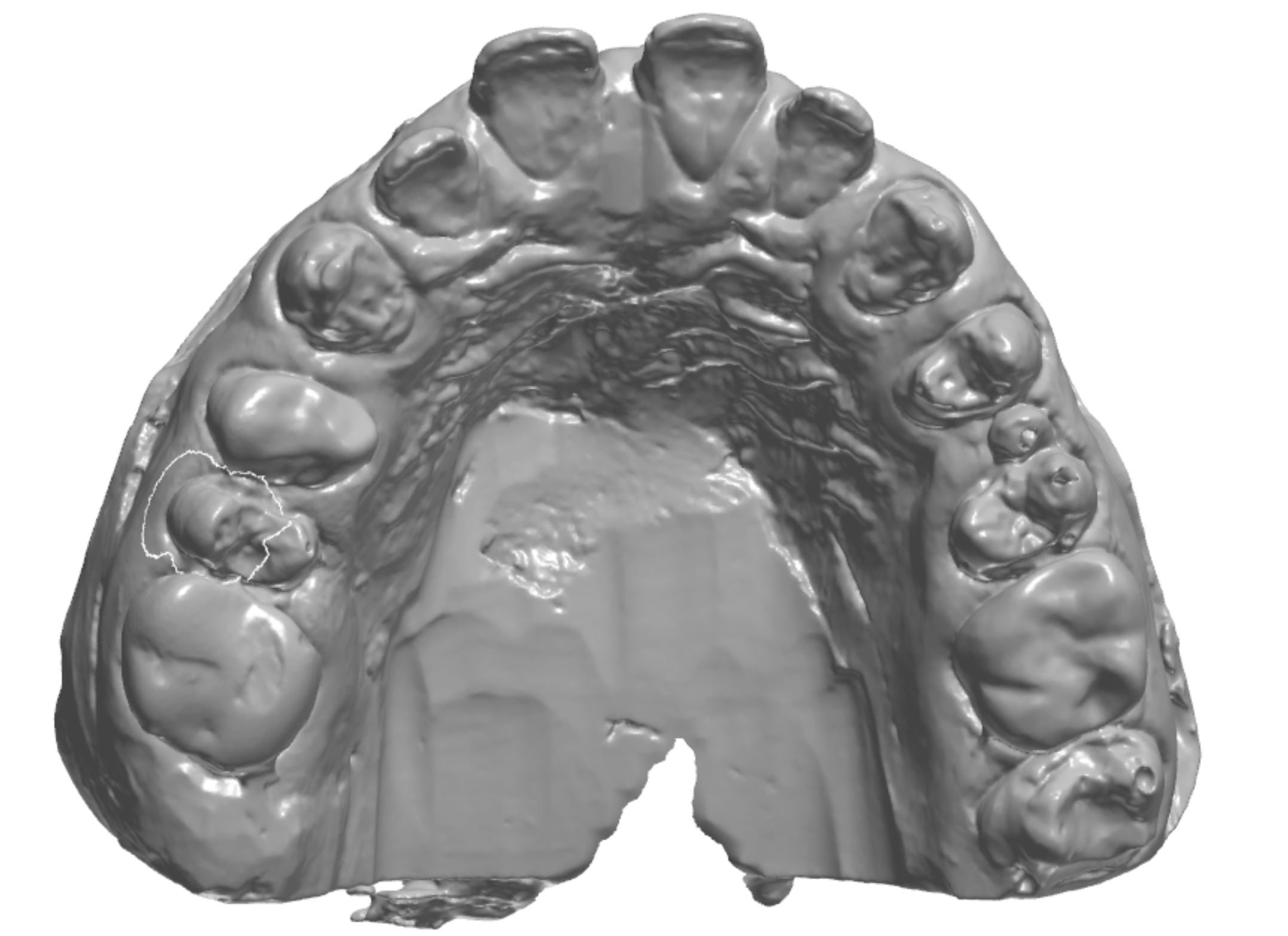
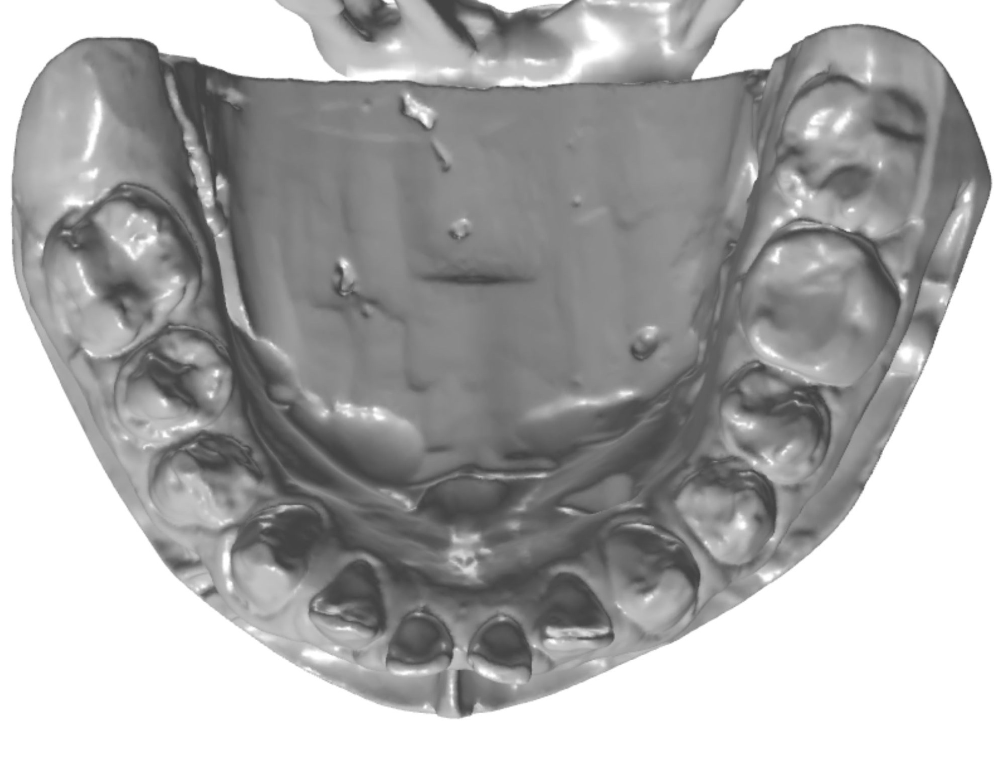
Figure 3a; Digitized pre-operative models.
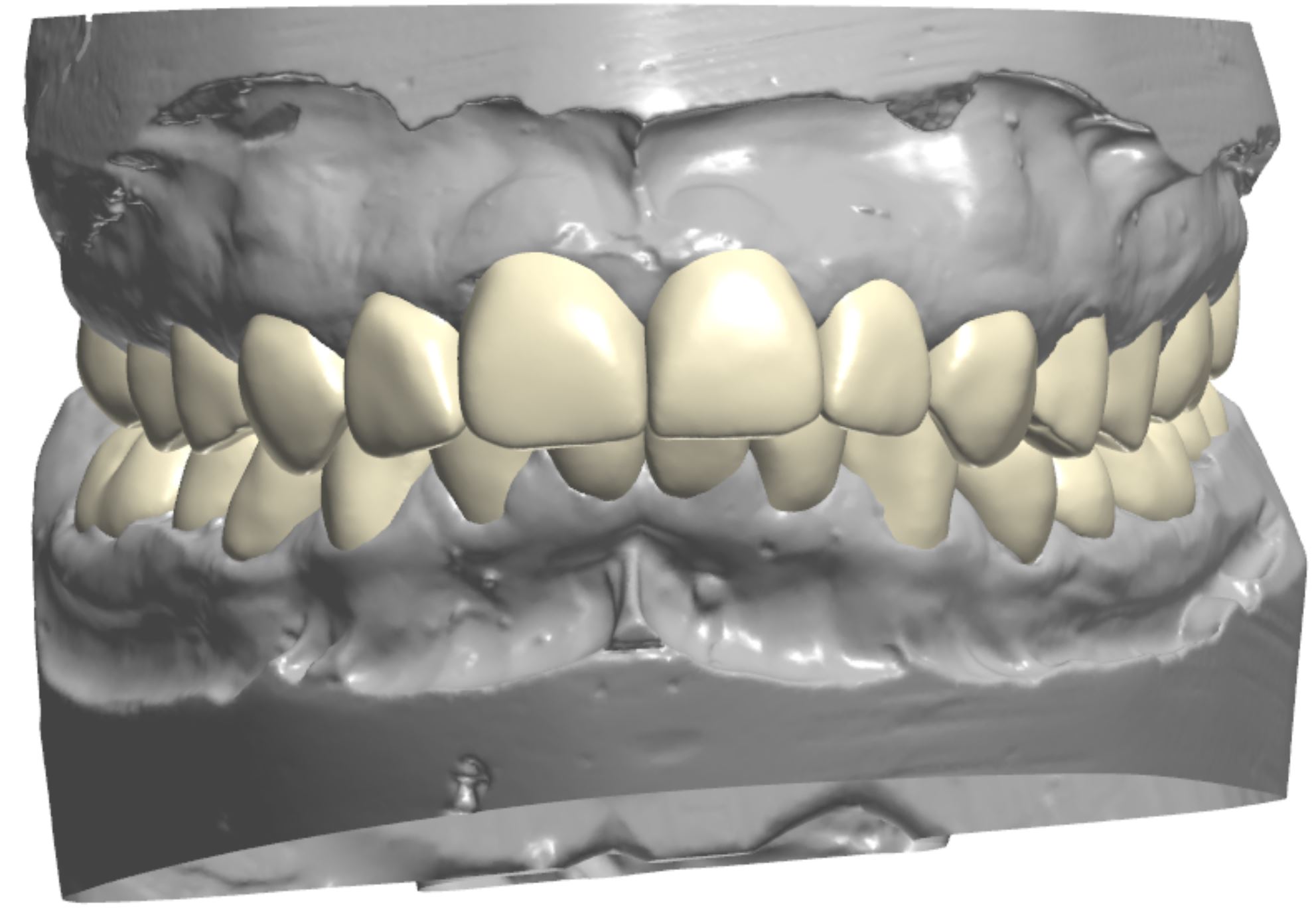
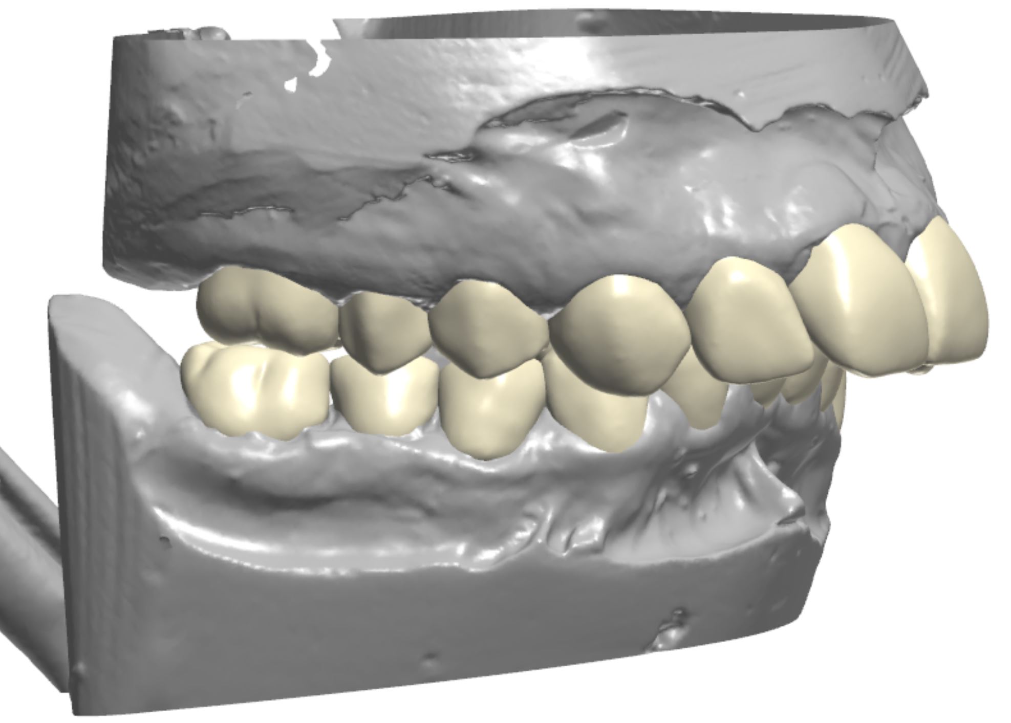
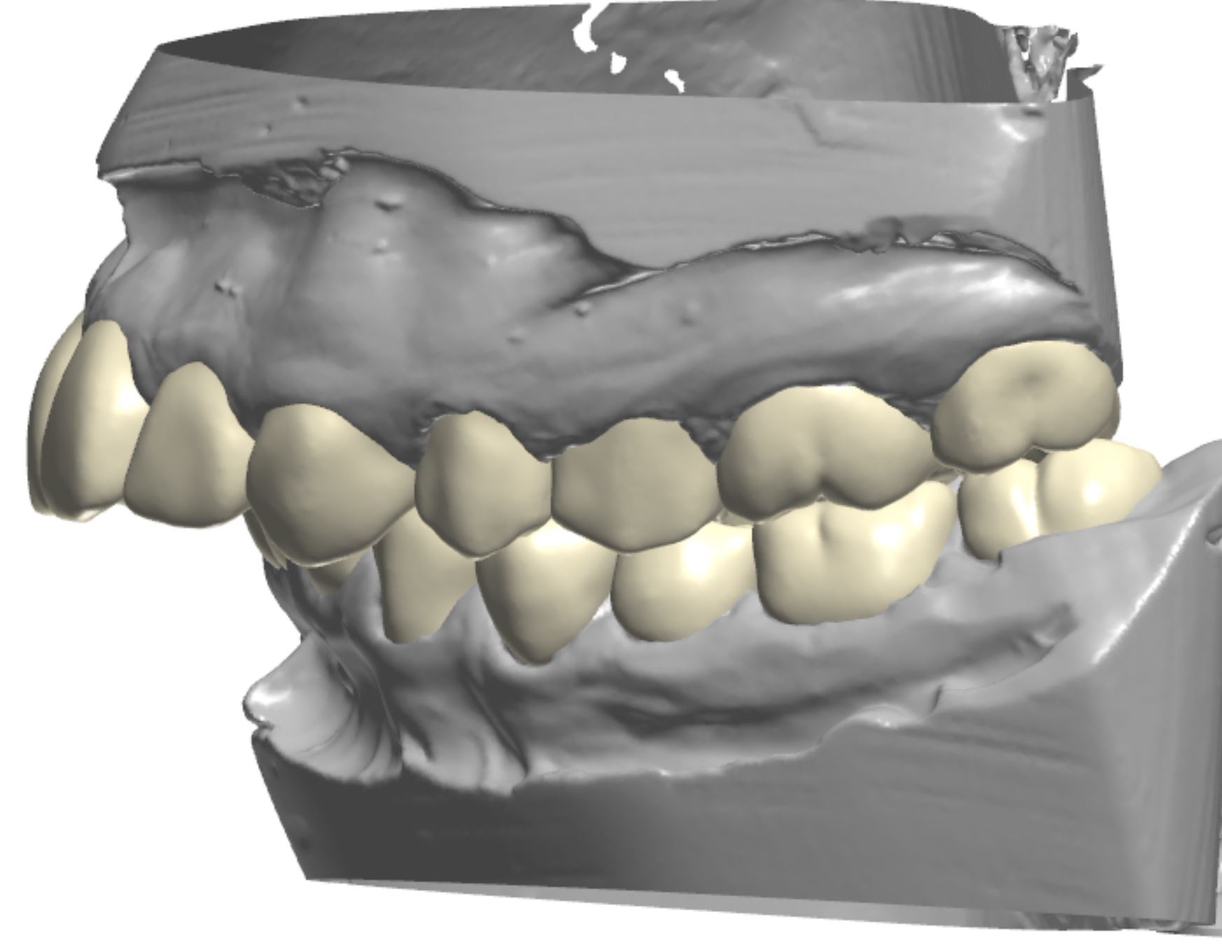
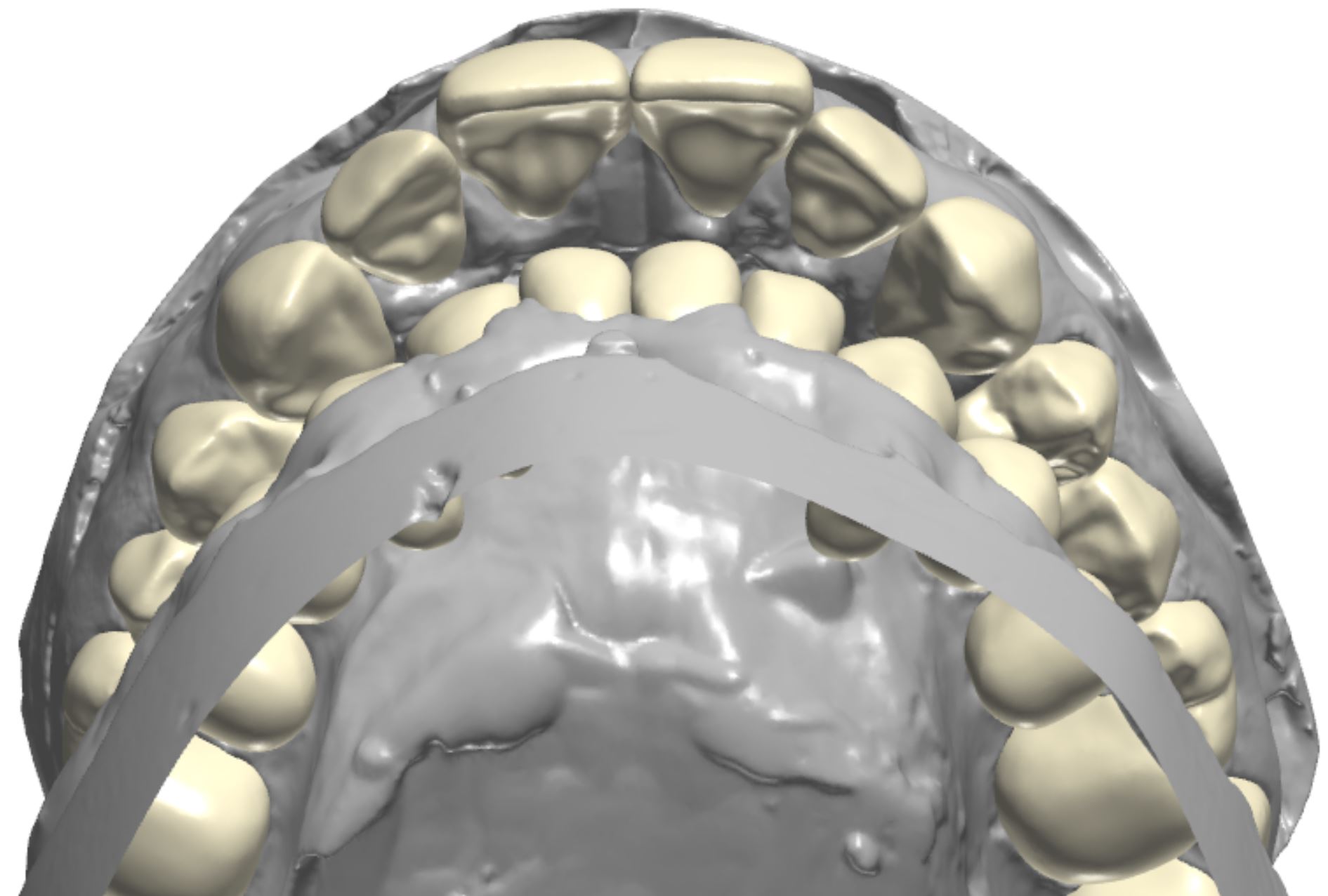
Figure 3b; CAD / CAM design of the case.
The main goals of the restorative plan were numerous and varied. Establishing oral health by removing compromised hard tissue was foundational to the success of the treatment plan. Restoring the teeth to proper form, function, and esthetics after the surgical removal of affected and infected hard tissue was considered essential to successful treatment. The restorative plan included not only esthetic correction within the limitations of the existing orthognathic condition, but also an increase in VDO to accommodate orthodontic movement of the anterior segments to correct the deep bite. The teeth needed to be restored individually to give the orthodontic provider control over root and tooth movement. Additionally, the teeth would need to be restored with a material suitable for accommodating adhesive bonding of orthodontic brackets. A final consideration in the initial restorative therapy was to provide the patient with semi-permanent restorations, as the changes to occur through orthodontic treatment and continued appositional growth would undoubtedly alter the location and presentation of the teeth within the maxillo-facial complex. Composite was selected as the most suitable restorative material to achieve the initial treatment goals. The patient was made aware that ideally, the composite crowns would be replaced sequentially with definitive dental ceramics after a proper orthodontic end point was achieved and growth was complete. Additionally, gingival plastic surgery was indicated to address the altered passive eruption, as 5-7 mm of soft tissue was present between the alveolar crest and gingival margin of multiple teeth. For initial therapy, gingivectomies with internal beveling and trans-sulcular crown lengthening would be performed to increase tooth length and maintain biological width (figure 4). Primary teeth O and P were incorporated into the restorative plan. It was decided these teeth would be retained as long as possible before extraction and definitive replacement with implants or a fixed partial denture. Initially, endodontics and removal of the supernumerary tooth conjoined to the mesial of tooth #13 was considered. After CBCT evaluation of pulp horn location, it was determined that the conjoined teeth would be treated as a single tooth, and preparation design would include the supernumerary tooth, despite a small esthetic compromise due to excessive mesial-distal width (figure 5a-b).

Figure 4; Representation of the dentogingival complex (biologic width).
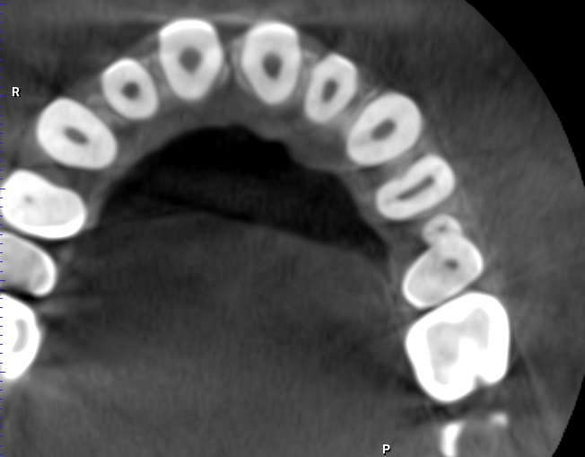
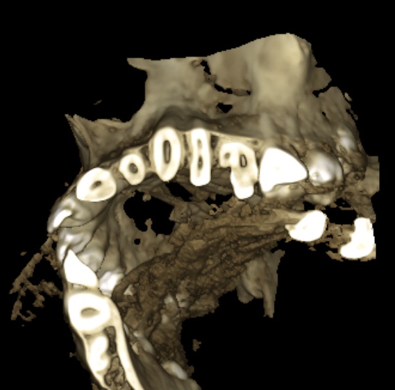
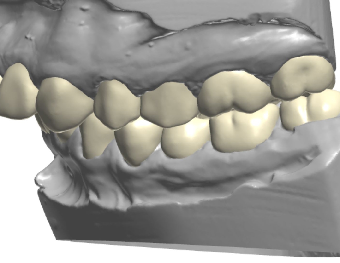
Figure 5a; CBCT evaluation of tooth #13 and conjoined supernumerary tooth, along with the proposed restoration design.

Figure 5b; The modified preparation of conjoined supernumerary tooth
It was decided that the restorative plan could be used to increase the VDO to facilitate orthodontic movement of the anterior segments by creating space. Although it is arguable that this should be the primary reason for an increase in VDO, it is important to consider that bite blocks would have been implemented to create a vertical increase anyway. Additionally, it was apparent that tooth structure had been lost due to caries, fracture, or attrition in the posterior, suggesting a collapse in verticality had occured, and that replacing the lost vertical dimension should be part of restoring the posterior teeth. Caution should be implemented in increasing the VDO of patients with Class II occlusion and deep bite. As the vertical dimension (overbite) is increased, so too is horizontal dimension (overjet). This can cause problems related to speech and mastication (especially incising food) if the increase is too great. For this patient, who initially presented with a severe overbite and is committed to undergoing orthodontic treatment to better relate the anterior segments, the potential for temporary negative effects was a tolerable risk to facilitate the final outcome. As previously stated, the VDO was increased largely to give the orthodontist room to re-position anterior segments of upper and lower teeth, thereby providing the operator and lab technician with only a broad target range of how much vertical space to create. General guidelines related to increasing VDO were followed, and a 4 mm increase in VDO was agreed upon by the general dentist and orthodontist.
To address the collapsed dentition and skeletal deep bite, the maxillary central incisors and maxillary canines provided key information for planning the case. Commonly, the central incisors can help discern the amount of vertical increase needed. As a guideline, a measurement taken from the Cemento Enamel Junction (CEJ) of the maxillary central incisor to the CEJ of the lower central incisor should be 16 - 18 mm in a Class I patient and 14-16 mm in a Class II patient. These measurements can provide guidelines (not justification) for the necessity and amount of vertical increase; if the CEJ - CEJ measurements are collapsed (less than the average values) an increase in VDO may be necessary (in a standard patient). The dimension of the patient’s central incisors was deficient, especially in length, and diastemas were present. The CEJ-CEJ measurement was only 11 mm (figure 6). Increasing incisal length was done minimally and judiciously to create symmetry, as the position of the central incisors and incisal edge in the patient’s face was appropriate. Tooth length gain could however be accomplished in an apical direction by performing gingivectomy with internal beveling. When sounding bone, it was discovered that the alveolar crest was located 4 - 6 mm from the gingival margin in the anterior segment, confirming that the actual CEJ of the maxillary central incisors is positioned more apically than the gingival margin would suggest. By relieving 3 mm of soft tissue and severing the connective tissue attachment, a 3 mm gain in tooth length could be achieved while still providing 3 mm for biologic width. In areas where 3 mm of space to accomodate biologic width was not available, a chisel was used to remove small amounts of the crestal bone through the sulcus (figure 7a-e). A new measurement from CEJ-CEJ would then be 14mm, which is more normative for a Class II patient. Only the canines were treated with plastic surgery at the time of initial treatment. Although evaluation of the dento-gingival complex relating to the central and lateral incisors was essential for treatment planning, it was decided surgery would be done after re-evaluation when a stable orthodontic endpoint was reached and growth was complete.


Figure 7a-e; a) Periodontal probe reading of the sulcular depth is 3 mm. b) When sounding bone, the periodontal probe reading approaches 6 mm. c) Gingivectomy to relieve excess tissue and contour gingival shroud (note the amount of enamel apical to the initial gingival margin posititon). d) Internal bevel to sever the connective tissue attachment. e) a bone chisel with a laser etched 3 mm marking to ensure adequate space for biologc width between the crestal bone and the new gingival margin position.
As detailed by Dr. Carl Misch, the canine position is a key indicator for planning tooth position relative to the maxilo-facial complex. Although some apical gain could be created by performing gingivectomy on the canines, it was clear that orthodontics would be required to continue apical movement to position the teeth (especially the canines) in the proper location. Although 3 mm worth of gingivectomy could help with the canine tooth length, apical gain alone would not be adequate to position the teeth correctly in the maxillo-facial complex. The acceptable range for canine exposure in relation to the maxillary lip line varies, but Misch found that the range of canine display in a lip at rest position varies far less than that of central incisors. Our goal for the patient was to have 0-1 mm of the canines visible in a lip at rest position. Gingivetomy with internal bevel and trans-sulcular bone removal was to be performed, but it was determined that the canine would still need to move apically 3 mm to be in the proper location in the face. Because the initial restorative phase would be interim in nature, the VDO change could be adjusted as necessary; either to accommodate orthodontic movement or to relieve possible TMD symptoms due to the patient being unable to accommodate the new VDO.

Figure 6; CEJ-CEJ measurement (11 mm) and maxillary right central incisor measurement (8 mm long x 8 mm wide).
Overall, the case was designed as a full mouth rehabilitation. The design included considerations related to tooth proportion, gingival zenith location, increased vertical dimension, esthetic correction, and stable occlusion. The plan was representative of initial therapy with the intention of being revisited after completion of orthodontic treatment.
Transfer of the plan to the patient’s dentition was completed using deliverables from the dental laboratory and composite resin. In the Computer Aided Design / Computer Aided Manufacturing (CAD / CAM) software, the complete design of the corrected maxillary and mandibular arches was printed using a 3D printer. Then, the initial design was altered so that only every-other tooth was corrected, while every-other tooth remained in its pre-operative state (figure 8). A set of models representing a correction of every-other tooth for each arch was also printed. Clear matirces were made on each set of models. Clinically, the patient was anesthetized, and soft tissue corrections were made using a 15C Scalpel and bone chisel. Next, every-other tooth was treated by removing unhealthy hard tissue before being prepared for the composite restoration. Retraction cord was placed in the gingival sulcus of the prepared teeth. The unprepared teeth adjacent to the prepared teeth were protected with strips of sterilized polytetrafluoroethylene (PTFE) tape to prevent unintentional adhesive bonding. A 37% phosphoric acid etch was used in a total etch technique, desensitizer (MicroPrime G, Danville) was applied to the prepared tooth structure and adhesive (Prime&Bond Elect Universal Dental Adhesive; Denstply Sirona) was applied for 20 seconds and light cured for 10 seconds. The clear matrix was fit over the unprepared teeth and shade A2 flowable composite (Herculite Ultra-flow Nano-hybrid; Kerr) was injected through a porthole created in the matrix prior to placement (figure 9a-d). The composite was cured through the matrix for 20 seconds on each surface; the excess material was trimmed and the restorations were contoured before the next set of teeth were prepared (figure 10a-b). This process was repeated for the remaining teeth. The occlusion was adjusted as necessary and the final composition was then polished. The patient was re-appointed for a 3-week re-evaluation to ensure the increase in vertical dimension was not problematic, and that stomatognathic functions such as eating, swallowing, and speaking were not compromised.
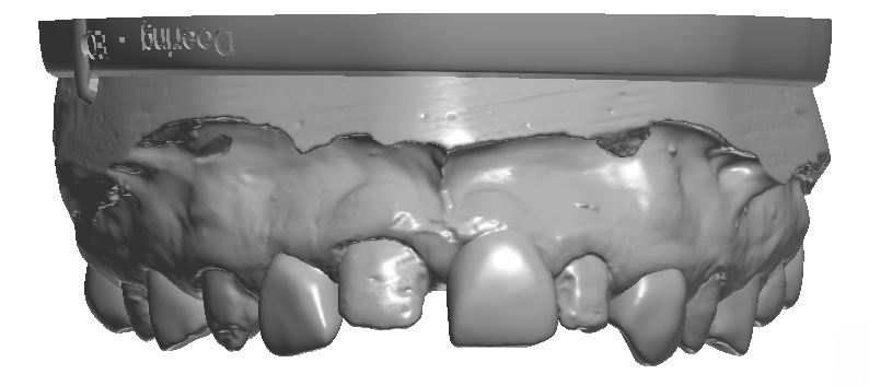
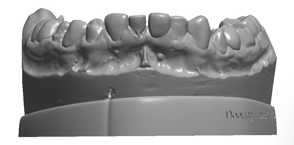
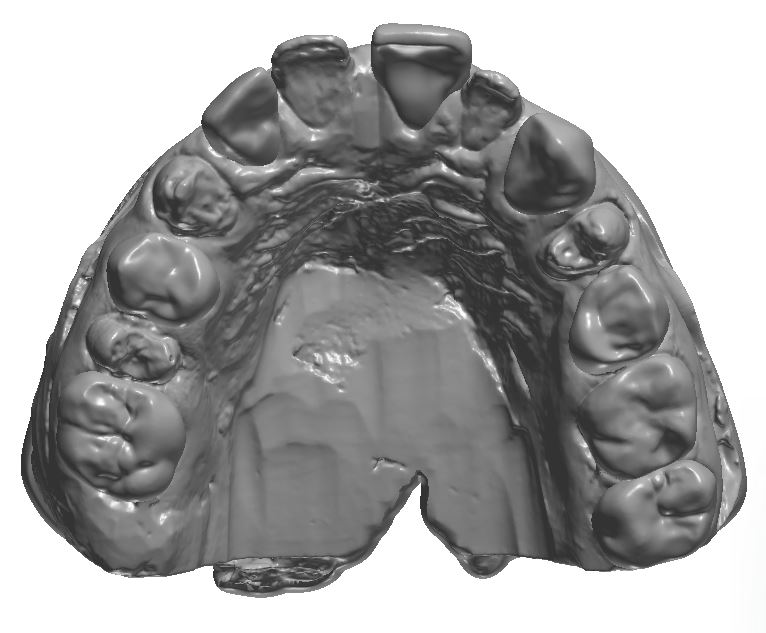
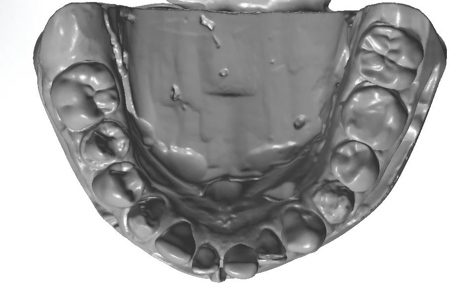
Figure 8; The “every-other” model in CAD / CAM software.


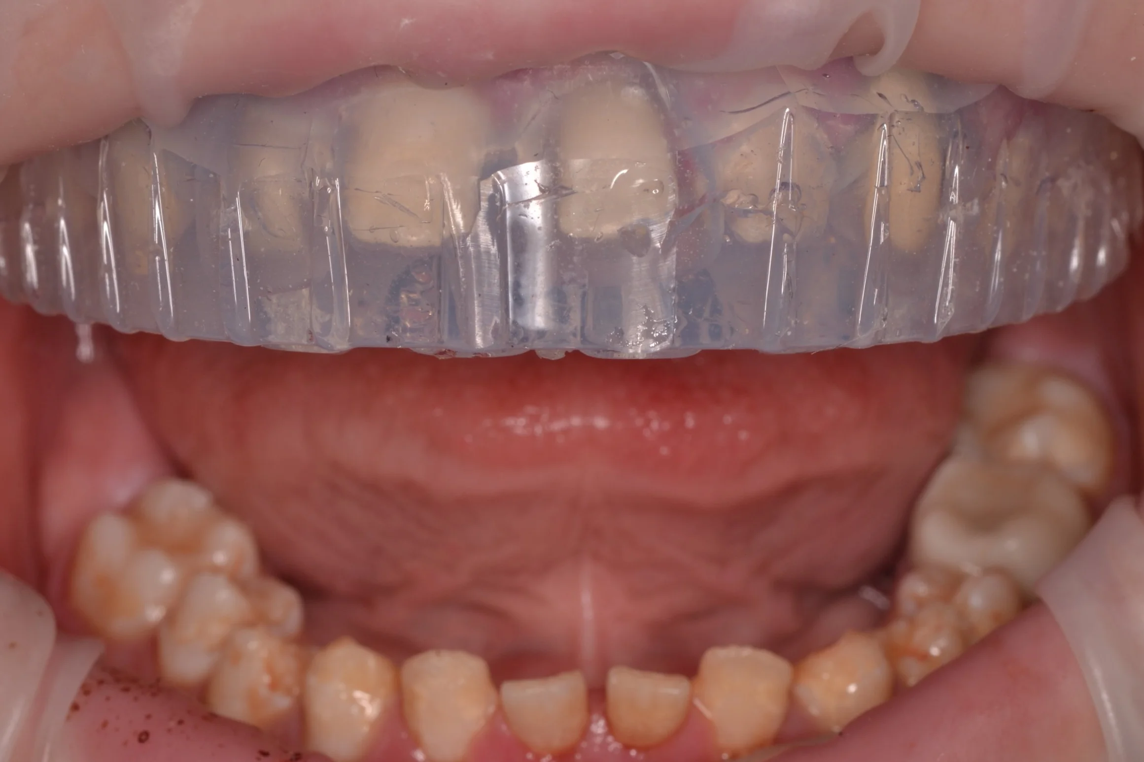

Figure 9a-d;

Figure 10a;

Figure 10b;
Ultimately, each tooth was restored individually to enable individual orthodontic root and tooth movement while providing a bondable substrate for orthodontic brackets. Although provisional, the restorations offered the patient immediate improvements in oral health, and in the form, function, and esthetics of his teeth. Furthermore, because the restorations are not considered definitive, the prototype is dynamic and able to be altered during continued restorative and orthodontic treatment; unlike dental ceramics, composite can be easily removed from or added to. Furthermore, the living prototype will provide valuable information before the dentition is to be definitively restored. Although cases like these require intensive planning pre-clinically and many chair hours clinically, the initial improvements are extremely rewarding. Given proper treatment planning and coordination between the operator, orthodontist, and lab, cases like this can be extremely fun to execute!

Dr. Ryan J. Yakowicz, DDS, FAGD
Dr. Yakowicz practices in the Greater Madison Area of South Central Wisconsin. Having completed over 775 hours of continuing education, his special interests include functionally cosmetic full mouth rehabilitation, TMD and oral-facial pain, and surgical implant placement and prosthetic restoration.
Dr. Yakowicz is currently the president of the Madison Dental Progress Forum Study Club and the Wisconsin Institute for Advanced Dental Education. He is a Fellow of the Academy of General Dentistry, and is a member of the American Academy of Cosmetic Dentistry, and the American Academy of Fixed Prosthodontics. Additionally, Dr. Yakowicz participates in research studies for the National Provider-Based Research Network and is an Ambassador to the National Health Service Corps.
References:
1) Spear, F (2006) Approaches to Vertical Dimension. Advanced Esthetics and Interdisciplinary Dentistry 2 (3): 2006: 2-12.
2) Kois, J, Phillips, K (1998) Occlusal Vertical Dimesnion: Alteration Concerns. Compendium 18 (12): 1998: 1169-1177.
3) Rivera-Morales WC, Mohl ND. Relationship of occlusal vertical dimension to the health of the masticatory system. J Prosthet Dent. 1991 Apr;65(4): 547-53.
4) Terry, Douglas A., Willi Geller, and Douglas A. Terry. 2013. Esthetic & restorative dentistry: material selection & technique. Chicago: Quintessence Pub. Co.
5) Misch, CE. Guidelines for maxillary incisal edge position-a pilot study: the key is the canine. J Prosthodont. 2008 Feb;17(2):130-134.
6) Terry D, Powers J, Blatz M. The Inverse Injection Layering Technique. Journal of Cosmetic Dentistry. 2018 Spring; 34 (1): 48-62.
7) Coachman, C. Emotional Digital Dentistry. Journal of Cosmetic Dentistry. 2019 Winter; 34 (4): 36-42.
8) Lyons, L, English, J. In Vitro Shear Testing of Orthodontic Bonding to Lithium Disilicate Ceramic. Journal of Cosmetic Dentistry. 2019 35 (1): 82-89.